Hydraulic and mechanical drawing presses, such as Schuler P2E and AIDA NC1, with deep drawing capabilities.
Metals (steel, aluminum, brass), and some plastics.
Max draw depth: 500mm. Tolerances: ±0.05mm.
Quality Management System: ISO 9001:2015 certified, ensuring high precision and quality.
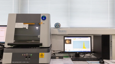
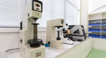
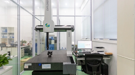
Inspection Equipment: CMM, tensile testing machines, and digital calipers.
Quality Assurance Process: Material verification, continuous in-process checks, and final inspection using CMM and tensile testers to ensure dimensional and structural integrity.
The wire drawing process is a fundamental technique in metalworking used to reduce the diameter of a wire while increasing its length. This process is essential for producing wires of various sizes and materials for applications in industries such as electronics, construction, and automotive. Here is a step-by-step guide to understanding the wire drawing process:
Preparation of the Wire Rod: The process begins with a wire rod, which is typically cleaned and coated to facilitate smooth drawing and reduce friction.
Pointing: The end of the wire rod is tapered to a point to allow it to pass through the drawing die.
Drawing: The pointed end of the wire is threaded through a drawing die, a tool with a precise hole that determines the final diameter of the wire. The wire is then pulled through the die using a drawing machine, which reduces its diameter and elongates it.
Intermediate Annealing (if necessary): For certain materials, intermediate annealing may be required to soften the wire and relieve internal stresses, making it easier to draw further.
Multiple Passes: Depending on the desired final diameter, the wire may need to pass through several progressively smaller dies. Each pass further reduces the diameter and increases the length of the wire.
Final Annealing (if necessary): After the final drawing pass, the wire may undergo a final annealing process to achieve the desired mechanical properties and flexibility.
Finishing: The finished wire is then cleaned, coated, or treated as required for its intended application.
By understanding each step of the wire drawing process, manufacturers can produce high-quality wires with precise dimensions and excellent mechanical properties, meeting the demands of various industrial applications.
In the context of metal rods and wires, the difference between forming and drawing becomes more specific to how the material is shaped and manipulated:
Forming: For metal rods and wires, forming refers to any process where the metal is shaped by applying force without necessarily changing its thickness or significantly elongating it. Forming can include bending, coiling, or shaping metal rods or wires into particular configurations. Some forming processes used for rods and wires include:
Bending: Shaping the wire or rod by applying force at specific points.
Coiling: Winding the wire into a spiral or helical shape.
Swaging: Compressing or hammering parts of a rod to change its diameter in specific areas.
Drawing: Drawing in the context of metal rods and wires is a specific process in which the material is pulled through a die to reduce its diameter while elongating it. The process involves stretching the wire or rod, making it thinner and longer. The metal rod or wire is typically drawn multiple times through progressively smaller dies to achieve a precise diameter and smooth finish. The key outcomes of drawing are:
Reduction in diameter: The thickness decreases as it is drawn through each die.
Increase in length: As the diameter reduces, the length increases, sometimes dramatically.
Enhanced properties: Drawing can strengthen the material through work hardening, improving tensile strength and durability.


